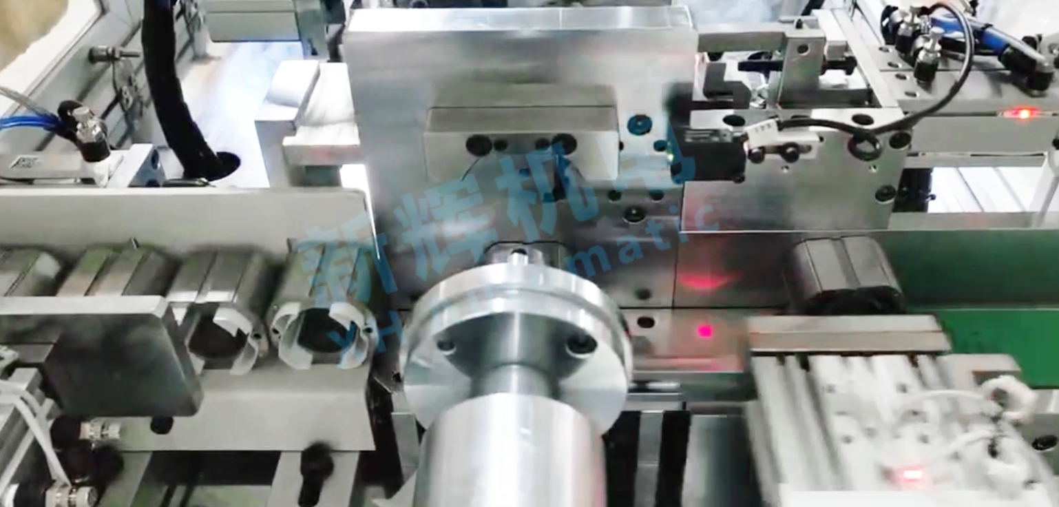
Series excitation motor motor stator automatic slotting paper machine what are the common control unit failure and solutions?
First, the programmable logic controller (PLC) failure
(A) fault phenomenon
Program operation error
Slot paper insertion sequence is chaotic, for example, there may be a part of the slot paper inserted first, and then skipped some stator slot, and then inserted into other slots, resulting in incomplete and uneven insertion of stator slot paper.
Equipment action is not coordinated, such as slot paper transfer and insertion action can not be correctly coordinated, there may be slot paper is still in the process of transferring the start of the insertion action, or slot paper insertion after the transfer mechanism has not yet stopped, resulting in damage to the slot paper or equipment clogging.
The equipment cannot be started or stops suddenly.
After pressing the start button, there is no response from the equipment, and the PLC's power indicator and run indicator may not light up or blink abnormally.
The equipment stops suddenly during operation and cannot be restarted by normal operation, and the PLC may display a fault code or no indication.

(ii) Cause analysis
Program error or loss
The program in the PLC may be incorrect or partially lost due to electromagnetic interference, power fluctuation, etc. In addition, the program may be lost when it is modified, modified, modified, modified, modified, or lost. In addition, improper operation when modifying or updating the program can also cause program failure.
Hardware Failure
The input/output (I/O) module of the PLC may malfunction. For example, the input module cannot receive sensor signals correctly, probably because the interface is damaged, the internal circuit is short-circuited or disconnected; the output module cannot control the actuator (such as motors, cylinders, etc.) correctly, probably because of damaged relays, transistor breakdowns, and so on.
Power module failure, such as unstable power supply, power module internal components are damaged, will lead to PLC can not work properly.
Communication Failure
If there is a communication problem between the PLC and other devices (e.g., HMI, sensors, actuators, etc.), it will affect the transmission of data and the giving of commands. Damaged communication lines, loose communication interfaces, or incorrectly set communication protocols can lead to communication failures.
(iii) Solutions
Program check and repair
Use the PLC programming software to re-download the correct program backed up to the PLC. If there is no backup, it is necessary to check and debug the program step by step to find out the wrong logic in the program, such as wrong setting of timer and counter, unreasonable conditional judgment statement, etc., and make corrections.
In the process of program modification or updating, operate in strict accordance with the operation manual to ensure the integrity and correctness of the program. At the same time, take electromagnetic shielding measures and install a regulated power supply to reduce the impact of electromagnetic interference and power fluctuations on the PLC program.
Hardware Repair and Replacement
For I/O module failure, use a multimeter and other tools to check the voltage, resistance and other parameters of the input and output interfaces to determine whether there is a short circuit or broken circuit. If the interface is damaged, you can try to replace the interface module; if it is an internal circuit failure, you need to replace the whole I/O module.
Check whether the output voltage of the power supply module is normal; if the power supply module is found to be damaged, replace the power supply module of the same model in time. After replacing the hardware, reconfigure and test the PLC to ensure that it can work normally.
Communication troubleshooting
Check whether the communication line is intact and whether the interface is loose. For loose interfaces, re-insert and fix them; for damaged communication lines, replace the lines with new ones.
Check the communication protocol settings to ensure that the communication protocol between the PLC and other devices is consistent. You can check the correct setting of the communication protocol by checking the device manual or consulting the device manufacturer. If the communication protocol is incorrect, reset the communication protocol parameters.
Second, the human-machine interface (HMI) failure
(A) Failure phenomenon
Abnormal display
The screen appears splash screen, black screen, white screen and other phenomena, can not normally display the operating status of the device, parameter settings and other information.
The display content is incomplete, part of the text, icons or data can not be displayed normally, affecting the operator's understanding of the equipment.
Touch function failure
When touching the screen, the equipment does not respond, and it is not possible to set parameters and give operating instructions through the human-machine interface.
(ii) Cause analysis
Hardware problem
The display of the HMI may be damaged due to long-term use, impact, or electrical failure. For example, damage to the backlight tube of the display will lead to a black screen, and failure of the liquid crystal display module will lead to phenomena such as splash screen.
Damage to the touch-sensitive components of the touch screen, such as wear and tear of the conductive layer of the touch panel, touch chip failure, etc., will lead to the failure of the touch function.
Software problems
Failure of the operating system or application of the human-machine interface may be due to program crash, file corruption or virus infection. This situation may lead to display abnormality or the touch function does not work properly.
Connection Problems
Loose, broken or short circuit of the connection line between the HMI and PLC or other control units may affect the data transmission, which may cause problems with the display and operation functions.
(iii) Solutions
Hardware repair and replacement
If the display is damaged, you need to replace it with a new one. For touch screen touch function failure, first check whether the connection line of the touch panel is normal, if normal, you may need to replace the touch sensing element or the whole touch screen.
After replacing the hardware, calibrate and test to ensure that the display can be displayed properly and the touch function of the touch panel is accurate.
Software Repair and Update
Try to repair the operating system and applications of the HMI. You can use the recovery function that comes with the device or reinstall the software to solve the problem of program crash or file corruption. At the same time, install antivirus software to check the device for viruses to prevent virus infections from causing software malfunctions.
Check and repair the connection line
Check the connection lines between the HMI and other control units, and re-plug and fix loose lines. Use a multimeter and other tools to check whether the lines are broken or short-circuited; if there is any problem, repair or replace the lines in time.
Third, drive failure (used to drive motors, cylinders and other actuators drive)
(A) Failure phenomenon
Abnormal action of the actuator
The motor speed is unstable or cannot reach the set speed, resulting in uneven slot paper transfer speed and insertion speed, affecting the quality of slot paper insertion.
The cylinder does not move smoothly, such as abnormal telescoping speed, inability to extend or retract, etc., which may result in untimely insertion of slotted paper or inability to insert.
Drive Alarm
The drive may display fault codes, such as over-current alarm, over-voltage alarm, under-voltage alarm, etc., suggesting a problem with the drive.
(ii) Cause analysis
Wrong parameter setting
Incorrect setting of parameters such as speed, torque, current, etc. of the drive may cause the actuator to fail to work properly. For example, the speed loop gain of the motor driver is set too high, which may cause the motor speed to be unstable.
Internal Circuit Failure
Damage to the drive's internal electronic components (e.g., power transistors, integrated circuits, etc.) may be caused by overloading, overheating, power supply fluctuations, etc. Damage to these components can cause the drive to fail to output control signals properly, resulting in abnormal actuator movement.
External Interference and Connection Problems
Electromagnetic interference in the surrounding environment may affect the normal operation of the driver, resulting in signal transmission errors. In addition, loose connection lines between the driver and the actuator, poor contact, or malfunction of the actuator itself such as motors and cylinders can also trigger alarms and abnormal movements of the driver.
(iii) Solution
Parameter adjustment
Check the user manual of the drive and readjust the parameters of the drive according to the requirements of the actuator and the actual operation of the equipment. For example, for the case of unstable motor speed, you can appropriately reduce the speed loop gain and adjust the current limit and other parameters so that the motor can run stably.
Internal circuit repair and replacement
When the drive displays an internal circuit failure alarm, professional personnel are required to inspect and repair the drive. Use professional tools to detect damage to internal electronic components, and for damaged components, use components of the same type for replacement. After repairing or replacing, test the drive to ensure that it is working properly.
Reduce interference and check the connection line
Take electromagnetic shielding measures, such as installing a shielding cover around the drive and using shielded cables, to reduce the effect of electromagnetic interference on the drive.
Check the connection lines between the drive and the actuator to ensure that the connection is firm and the contact is good. At the same time, check the actuators (motors, cylinders, etc.) to eliminate faults in the actuators themselves.
※ If the above ways and means still can not solve the equipment failure, please contact Xinhui Electromechanical Equipment Co., Ltd. technical specialists through the page chat tool to seek help.


