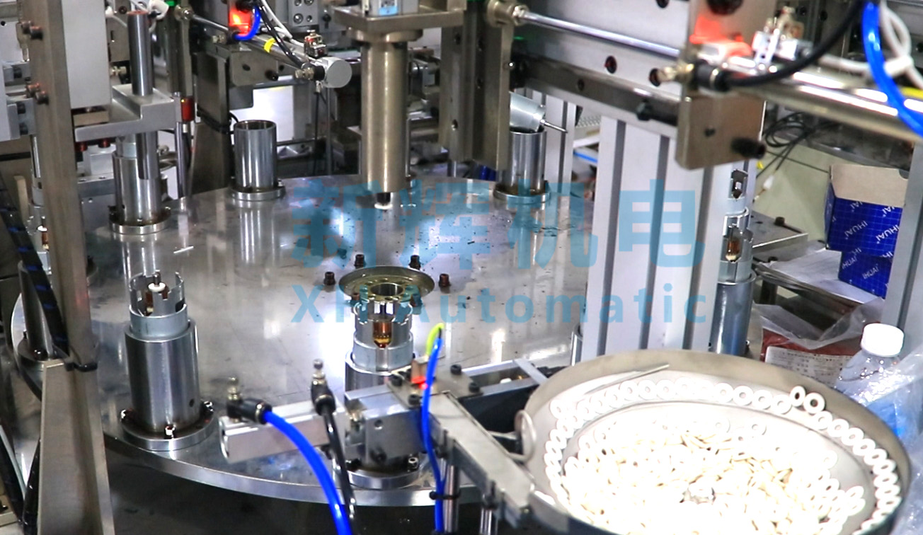
How to fault analyze and troubleshoot motor motor rotor automatic meshing machine?
First, fault analysis steps
(A) observe the fault phenomenon
l observation of the overall operating status of the equipment
First of all, check whether the equipment can start normally. If it can not start, pay attention to observe whether the power indicator, the relay and contactor in the control box have action, as well as whether there is an abnormal sound or odor.
For the case of being able to start but running abnormally, observe whether the running speed of the equipment is stable, such as whether the rotor transfer speed is fast or slow, and whether the action of the meson mounting mechanism is smooth. At the same time, pay attention to whether there are abnormal vibration and noise during the operation of the equipment, for example, whether there is harsh friction sound, periodic impact sound, etc..
l Observation of meson installation
Check the positional accuracy of the meson installation. Observe whether the meson is installed in the correct position of the rotor and whether there is axial or radial deviation. You can use a gauge (such as calipers, a percentage meter) to measure the degree of deviation of the meson installation position from the standard position.
Check the installation quality of the meson. Check whether the meson is firmly mounted on the rotor, e.g., by manually rotating the rotor and feeling whether the meson is loose; or observe whether the meson will fall off during subsequent simulated operation (if the equipment has this feature) or actual motor assembly tests.

(ii) Collection of fault information
l Equipment operation data collection
Check the operation data records in the operation interface or control system of the equipment. These data may include the rotational speed and torque of the motor, the status of the detected signals of the sensors, and the operating parameters of the various actuators (e.g., cylinders, motors, etc.). Analyze these data to see if they are within normal limits, e.g., if the motor speed matches the set value and if the sensor signals are feeding back properly.
If the device is equipped with a fault diagnosis system, check the fault code display. Different fault codes correspond to different types of faults, for example, a particular fault code may indicate a sensor failure, while another may represent a motor overload. Make a preliminary judgment of the general scope of the fault based on the fault codes.
l Ask the operator
Talk to the operator of the equipment to find out how the equipment was operating before the fault occurred. Ask whether any special operation has been carried out, such as modification of equipment parameters, replacement of new rotor or dielectric type; whether any abnormal phenomenon has occurred, such as brief shaking of the equipment, alarm prompts on the operation interface, etc. The operator's feedback may provide information about the motor's performance, and may also provide information about the motor's performance. Feedback from the operator may provide important clues to help quickly locate the cause of the fault.
(iii) Analyze the cause of failure
l Mechanical Cause Analysis
Check the transmission components. If the equipment runs at an unstable speed or has abnormal noise, the transmission belt, chain, gears and other components may be worn, loose or jammed. For example, belt wear will cause the belt to slip, making the transmission speed unstable; gear tooth surface wear is serious may produce periodic impact sound.
Check the positioning and clamping mechanism. Inaccurate positioning of the rotor or deviation of the meson mounting position may be caused by a worn positioning pin or block, or insufficient or uneven clamping force of the fixture or jaws. For example, worn positioning pins reduce the accuracy of rotor positioning during transfer.
Check the mounting tool head. Poor meson mounting quality may be the result of wear, deformation or damage to the mounting tool head (e.g., press-fit head, screwing head). For example, a worn press-fit head may not be able to provide enough pressure to securely mount the meson.
l Electrical Cause Analysis
Check the transducer. If the unit is operating abnormally or the dielectric is mounted in an inaccurate position, the photoelectric sensor, Hall sensor, or proximity sensor may be faulty. Sensor failure may be due to surface contamination, internal component damage or signal transmission line problems. For example, a photoelectric sensor with a dust-covered surface may not accurately detect the rotor position, resulting in a biased meson mounting.
Check the motor and drive. Abnormal motor operation (e.g., erratic speed, no start, etc.) may be due to shorted or broken windings in the motor itself, damaged brushes (for brushed motors), or a faulty motor driver. A faulty motor driver may be caused by damaged electronic components, incorrect parameter settings, etc.
Check the control unit. A malfunction of the PLC (Programmable Logic Controller) or other control module may cause the entire operating logic of the unit to be confused. The cause of the malfunction may be a program error, hardware damage, or communication failure. For example, the PLC's input/output interface is damaged and may not be able to properly receive sensor signals or control actuators.
Second, common troubleshooting methods
(I) Mechanical Troubleshooting
l Troubleshooting of transmission parts
Worn belts or chains should be replaced promptly. When replacing, make sure the model of the new belt or chain is the same as the original part, and adjust the tension according to the requirements of the equipment. If the gears are worn or damaged, replace the corresponding gears, and check the meshing of the gears and adjust the meshing gap to the proper range.
If the transmission parts are loose, check and tighten the connection screws. For loose couplings, reinstall and adjust the axial and radial deviation to ensure a firm connection and smooth transmission.
l Troubleshooting of positioning and clamping mechanism
Replace worn positioning pins, blocks, clamps and jaws. After installing new positioning and clamping components, carry out an accuracy calibration. For example, adjust the positional accuracy of the positioning mechanism by using a standardized rotor model, and adjust the clamping force of the fixture to the specified range by using a pressure test tool.
l Mounting tool head troubleshooting
For worn or deformed mounting tool head, replace the tool head with a new one. After replacement, carry out the position and pressure (or torque) calibration of the mounting tool head. Professional calibration equipment can be used, such as pressure sensors and position calibrators, to ensure that the installation parameters of the tool head meet the requirements.
(ii) Electrical troubleshooting
l Sensor troubleshooting
Clean the sensor surface of dust, oil and other contaminants. If the internal components of the sensor are damaged, replace the sensor with the same model. After replacement, calibrate and debug the sensor to ensure that its detection accuracy and signal transmission is normal. For example, for photoelectric sensors, adjust their sensing distance and sensitivity so that they can accurately detect the rotor position.
l Motor and drive troubleshooting
For motor failure, check the resistance value of the motor winding (using a multimeter), and repair or replace the motor if a short circuit or broken circuit is found. For brushed motors, check the wear and tear of the brushes and replace those that are badly worn. For motor drive failures, check its internal electronic components for burn marks, and replace damaged components if any. At the same time, check whether the parameter settings of the driver are correct, such as speed, torque and other parameters in line with the equipment requirements.
l Control unit troubleshooting
If the PLC program is wrong, use the programming software to check and modify the program. After backing up the original program, re-download the correct program to the PLC. For PLC hardware faults, such as input/output interface damage, replace the corresponding module. Check whether the communication line between control units is normal, if loose or damaged, repair or replace the communication cable. At the same time, make sure that the communication protocol is set correctly so that each control unit can communicate with each other normally.
※ If you still can not solve the problem by the above ways and means, please contact the technical specialists of Xinhui Mechanical & Electrical Equipment Co.


