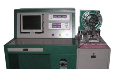
What are the common control unit failures and solutions for DC motor motor automatic tester?
1, controller hardware failure
l Chip damage
Failure phenomenon: the tester completely loses the control function, cannot start the test program, or suddenly stops working during the test. The indicator light of the control unit may appear abnormal flashing or not light up at all.
Cause analysis: may be due to power surge, electrostatic discharge, overheating or long-term use of the chip internal circuit damage.
Solution: First check whether the power supply is stable, to rule out the possibility of power supply problems causing damage to the chip. If the chip itself is damaged, it needs to be replaced by professional technicians using professional tools. After replacing the chip, system configuration and calibration may need to be performed again.

l Circuit board short circuit or broken circuit
Failure phenomenon: Some functions of the tester fail, such as some test parameters can not be set, or the control signal of the motor (such as speed control, torque control) is not stable. The equipment may have intermittent failures, sometimes working normally, sometimes abnormal.
Cause analysis: Components on the circuit board may be short-circuited or disconnected due to overheating, humidity, or physical damage (e.g., solder joints falling off, wiring being scratched).
Solution: Carefully check the appearance of the circuit board and look for burn marks, loose solder joints or broken lines. For short-circuit points, insulating tools can be used to isolate the short-circuited portion; for broken circuit problems, it is necessary to re-solder the line or replace the damaged part of the line. After dealing with the circuit board problem, to carry out all the function tests to ensure that the fault is completely eliminated.
2, control software failure
l program crash or crash
Failure phenomenon: control software in the process of running suddenly stop responding to the interface appears stuck, or the software automatically shut down and pop-up error message box.
Cause analysis: the software may have loopholes or compatibility problems, such as incompatible with the operating system update, the software's own code errors or poor memory management leads to program crash.
Solution: Try restarting the test machine and the control software. If the problem persists, check if there is an updated version of the software, download and install new software patches or updates from official channels. If the software crashes frequently, contact the technical support team of the software supplier to provide detailed error information (such as error code, operation steps in which the failure occurs, etc.) in order to obtain a more accurate solution.
l The parameters are set incorrectly or cannot be saved
Failure phenomenon: When setting test parameters (such as the target speed of the motor, torque range, test time, etc.), the software fails to recognize or save the set parameters correctly, resulting in the test not being carried out as expected.
Cause analysis: The parameter setting module of the software may be faulty, or the database file for storing parameters may be corrupted. It is also possible that the user privileges are insufficient to modify and save the parameters.
Solution: First, check the user rights settings to ensure that you have sufficient rights to operate the parameter setting function of the software. If the permission is normal, try to restore the default parameter settings of the software to see if the problem can be solved. If the database file is corrupted, you can try to use the database repair tool that comes with the software (if available), or reinstall the software to restore the parameter setting function. After reinstallation, re-enter the correct parameters and test.
3、Communication failure
l Interruption of communication with external devices
Failure phenomenon: the tester can not receive commands from external devices (such as host computer, remote monitoring equipment), or can not send test data to external devices. For example, the host computer cannot control the tester to start the test, or cannot obtain the test report generated by the tester.
Cause analysis: Communication lines (such as network cables, serial cables, USB cables, etc.) may be loose, damaged, or have poor interface contact. Communication protocol settings may be incorrect, or the baud rate, data bits, stop bits and other parameters of the communication device do not match.
Solution: Check whether the communication line is firmly connected and whether the line is broken. If it is wireless communication, check the signal strength and network settings. Ensure that the communication protocols and parameter settings of both sides of the communication are exactly the same, including baud rate, data bits, stop bits, parity mode and so on. If the communication parameters are correct but still cannot communicate, you can try to replace the communication line or interface, or restart the communication equipment.
l Internal communication failure (between multiple control modules)
Failure phenomenon: different control modules inside the tester (such as motor drive module, sensor data acquisition module, data processing module, etc.) can not communicate properly with each other, resulting in some of the functions of the tester can not work together. For example, the motor has been started, but the sensor cannot transmit data to the data processing module for analysis.
Cause analysis: Failure of internal communication lines (such as internal wiring, communication lines on the circuit board), or damage to the communication interface of each control module. It is also possible that there is a conflict or error in the internal communication protocol.
Solution: Check whether the internal communication lines are connected normally, and see whether there are short circuits, broken circuits or poor contacts in the lines. Use professional communication detection tools (such as oscilloscopes, logic analyzers, etc.) to check whether the communication signal is normal. For modules with damaged communication interfaces, the communication interface needs to be replaced or repaired. If it is a communication protocol problem, you need to re-check and re-configure the internal communication protocol to ensure that each module can communicate correctly with each other.
※ If the above ways and means still can't solve the equipment failure, please contact the technical specialist of Xinhui Electromechanical Equipment Co.


