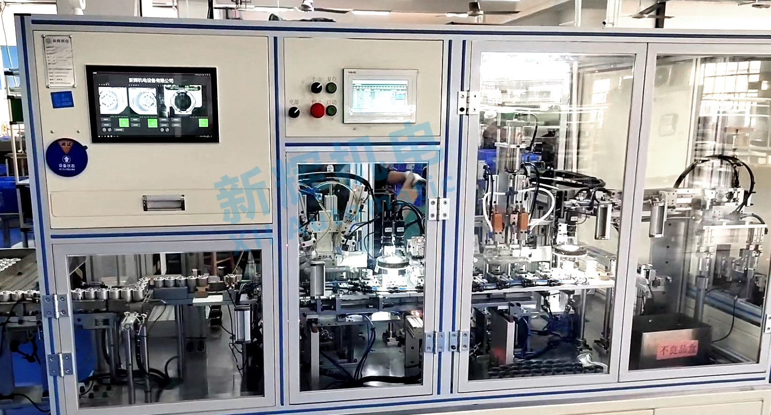
What are the common control unit faults and solutions for DC brushed motor motor fully automatic case tile assembly machine?
1, program logic error fault
l Fault phenomenon:
Magnet tile assembly sequence is confused, for example, the assembly machine may skip the assembly steps of some magnet tiles, or repeat the assembly of the same position, resulting in incomplete or incorrect assembly of the housing magnet tile.
Equipment action is not coordinated, for example, tile transfer and assembly action can not be correctly coordinated with each other, there may be the case that the assembly of the tiles starts before the tiles are completely in place, or the tiles can not be transferred away in time after the assembly is completed.
l Cause analysis:
Programming error is one of the common reasons. When writing the control program, the actions performed by the equipment may not be in accordance with the expectation due to wrong logic judgment conditions, improper setting of the loop structure and so on.
Compatibility problems may occur after the software is updated. The new program code is incompatible with the old hardware or other relevant software modules, resulting in the control unit not being able to correctly interpret and execute instructions.
l Solution:
For program logic errors, check through the debugging tool of the control software. You can set breakpoints and gradually observe the variable values and execution paths of the program at key steps to find the location of logical errors and correct the code. For example, check the code segment that controls the assembly sequence of tiles to see if there is a conditional judgment error that causes the assembly sequence to be disordered.
Perform all compatibility tests before updating the software. Run the updated software, the original hardware devices, and other related software simultaneously in the test environment to check for incompatibility. If incompatibility problems are found, adjust the software, which may involve modifying the software interface, adjusting the data reading and processing, etc., to ensure that the software and hardware and other software can work in coordination with each other.

2, parameter setting error fault
l Fault phenomenon:
The assembly speed is abnormal, such as the magnet tile transfer speed or assembly speed is too fast or too slow. Too fast speed may lead to inaccurate positioning of the magnetic tile or even collision damage; too slow speed will reduce the working efficiency of the equipment.
Problems with assembly accuracy, such as excessive deviation of the assembly position of the magnetic tile and the housing, may be caused by the wrong setting of the parameters related to the assembly position.
l Cause analysis:
The operator may have accidentally entered wrong values during equipment commissioning or parameter adjustment. For example, the parameter of the tile transfer speed is set to a value that is outside the reasonable range.
Mismatch of parameter units may also cause problems. In the control unit, different parameters may have different unit settings. If the operator does not pay attention to the units when setting the parameters, it may result in the actual set parameters not matching what is expected.
l Solution:
Double-check the parameter settings in the control unit that are related to assembly speed, position, etc. You can refer to the operation manual of the device to determine the correct parameter range and default values. According to the checking results, correct the wrong parameters to the correct values. After correcting the parameters, carry out a device test and observe whether the assembly speed and accuracy return to normal.
In the software interface of the control unit, the unit of each parameter is clarified and a unit conversion function is provided (if required). Limit the setting of important parameters, such as setting the upper and lower limits of the parameters, to prevent the operator from entering values that are beyond a reasonable range. At the same time, provide the default parameter values as a reference to facilitate the operator to set the parameters correctly.
3、Communication Failure
l Fault phenomenon:
There is no normal communication between the control unit and other equipment components (such as sensors, drives, etc.), resulting in the equipment being unable to obtain sensor data or unable to control the drive work. For example, the control unit is unable to receive signals from the tile position sensor, preventing the assembler from accurately determining the tile position.
Communication interruptions or data transmission errors may cause the equipment to move incorrectly or stop operating. For example, an error in sending speed control commands to the Motor Driver causes the motor to rotate abnormally.
l Cause analysis:
Damage to the communication line, such as loose, broken, or aging connecting wires, affects the quality and stability of signal transmission.
Incompatible communication protocols, when the control unit and other equipment components use different communication protocols or inconsistent protocol versions, communication failures may occur.
Electromagnetic interference may also interfere with communication signals, resulting in communication errors. Other electrical equipment around the device, sources of electromagnetic radiation, etc. may affect the signals in the communication line.
l Solution:
Check the communication lines to ensure that the connecting lines are firmly connected and are not broken or aged. For damaged lines, replace the lines with new ones in time. A professional cable tester can be used to check the connectivity and signal quality of the line.
Check the communication protocol settings to ensure that the communication protocol between the control unit and other equipment components is consistent. If the protocols are incompatible, it is necessary to configure the equipment to use the same communication protocol or perform protocol conversion.
For electromagnetic interference problems, take shielding measures for communication lines, such as using shielded cables, and ensure that the shield is well grounded. At the same time, the equipment and may produce electromagnetic interference source to maintain a certain distance, or the source of interference to take shielding, filtering and other measures to reduce its electromagnetic interference to the outside world.
4, control unit hardware failure
l Failure phenomenon:
Control unit is dead or no response, the indicator lights on the equipment panel does not light up or the operation button fails, the equipment can not start or stop normally.
Some of the functional modules of the control unit is damaged, such as input and output interfaces are damaged, resulting in failure to receive or send signals. For example, the control unit fails to output the correct signal to control the action of the tile assembly tool.
l Cause analysis:
Hardware aging is a possible cause. After long-term use, the electronic components (such as chips, capacitors, resistors, etc.) in the control unit may be aging and deteriorating in performance.
Power supply problems may also lead to hardware failure, such as too high or too low power supply voltage, excessive power supply fluctuations, power supply short circuit, etc., may damage the electronic components in the control unit.
Environmental factors, such as high temperature, excessive humidity, excessive dust, etc., may affect the normal operation of the control unit and lead to hardware damage.
l Solution:
For aging hardware components, professional maintenance personnel are required to use professional tools to detect and replace them. You can find the corresponding faulty components and replace them with components of the same model according to the maintenance manual of the device.
Check the power supply, use a voltmeter to measure the power supply voltage to ensure that it is within the rated voltage range of the control unit. If there is a problem with the power supply, repair the power supply unit or install a voltage regulator, UPS, etc. to provide a stable power supply.
Improve the working environment of the control unit, keep the ambient temperature and humidity within the appropriate range, and regularly clean the dust inside and outside the control unit to prevent the accumulation of dust on the hardware damage.
※ If the above ways and means still can not solve the equipment failure, please contact Xinhui Electromechanical Equipment Company Limited technical specialists through the page chat tool to seek help.


