Motor design basically contains three elements: magnetic energy design, magnetic circuit design and input power design of three parts, with a relatively simple permanent magnet motor to illustrate, magnetic energy design is the magnet specifications of the selected and configured to install the design; input power design for the selected enameled wire diameter and the number of turns and other specifications; magnetic circuit design is to select the characteristics of the permeability of the magnetic material and the size of the specifications of the part.
The ability of the motor depends on the specifications of these three elements, which often have a greater impact on the magnetic circuit design, once the design of the size of the magnetic guide material, the motor's assortment of output capacity has already been determined, even if the magnets or electrical energy to strengthen, can not be effective in obtaining the output capacity.
Why the influence of the magnetizing material is so important
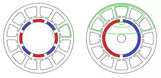
Magnetic lines of force are generated by the magnets on the rotor of the motor, and are transmitted to the stator through the permeable material, where they interact orthogonally with the power coils on the stator to generate torque, which is the source of the motor's rotational power. However, the magnetic flux density of the permeable material is limited, and the material that can accommodate more magnetic force is silicon steel sheet, which is also the most commonly used permeable material in motors.
Once the flux density of the silicon steel sheet reaches saturation, the extra magnetic force will become strung everywhere, and cannot effectively flow through the stator and power coils to generate torque application, which is regarded as leakage flux.
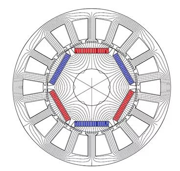
Schematic diagram of the internal magnetic circuit of a motor
In the case that the magnetic material has been selected, the flux density per unit area has been determined, and the rest is the design of the relevant dimensions, that is, the size of the silicon steel sheet, which is often discussed in the design of motors. If the inner and outer diameters have been determined, the main work includes three directions, first, is to assemble a small area to achieve assortment of magnetic flux density conduction; second, is to avoid the generation of leakage flux; third, is not to affect the flux demand, to increase the slot area, in order to accommodate more electrical energy conductor use.
How to design rotor geometry
Motor stator silicon steel sheet as an explanation of the design of each part of the main points, roughly divided into three parts, respectively, for the teeth, yoke, boots, assortment of motor magnetic circuit design, often with the help of software simulation, in order to achieve assortment of design requirements and results.
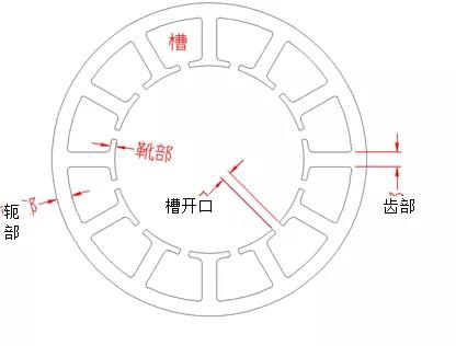
Stator silicon steel sheet parts schematic diagram
Yoke part: there are three things to pay attention to the design, respectively, for the magnetic flux density, mechanical strength and riveting point problem, first by the assortment of simple riveting point design, basically we should first consider the weight of the silicon steel sheet stacked to determine the number of rivets, too many rivets will affect the magnetic force through the number of mechanical strength problems, reasonable riveting strength, riveting point number the less the better. The following diagram shows that the direction of riveting points should be consistent with the direction of magnetic flux to reduce the degree of influence on the magnetic flux.
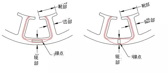
Rivet point direction design diagram
Magnetic flux density and mechanical strength are affected by the total width of the yoke. The wider the yoke is, the better the mechanical strength is, which can avoid the vibration and noise caused by the deformation of the silicon steel sheet under the influence of the magnetic force; and at the same time, avoiding the situation of over-saturation of the magnetic force, so as to achieve the effect of reducing the iron loss. Neglecting the mechanical strength and considering only the width of the flux demand of the assortment, the width of the yoke, the width of the teeth and the slot pole of the motor are equipped with a basic formula.
First of all, we need to know the relationship between the motor's slots and poles, that is, a pole will correspond to the number of teeth to determine the relationship between the yoke section and the tooth section. The following chart as an example, then the left side of the stator yoke will flow through the magnetic flux and a single tooth part of the same, then assorted yoke part of the demand for the width of the same width with the teeth can be; right example, the yoke part of the assorted dense will flow through the magnetic flux of the three tooth part, so the yoke part of the assorted width for the tooth part of the width of the triple, for a reasonable relationship.
Slot Polarization and Yoke Magnetic Flux Schematics
Boot: The basic design is based on the two parts of the slot opening and boot depth, the main influencing factor is the design of the slot opening, the smaller the slot opening, the better, which is conducive to the absorption of the magnetic force generated by the magnet, but too small will also produce magnetic leakage phenomenon. The slot opening is mainly affected by the winding requirements and has to be wound larger, so the design conditions may vary depending on the winding method.
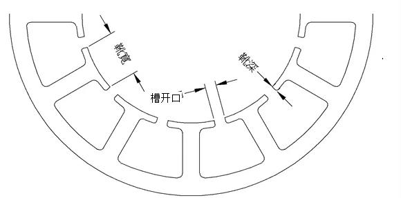
Diagram of boot related terms
If the slot opening is inward, it is usually produced by either an in-winder or an in-winder, which requires a larger slot opening width; an in-winder requires a slot opening width of about 1/3 of the total coil diameter, while an in-winder, depending on the design of the bobbin tube, is usually three times the diameter of the enameled wire but with an assortment width of more than 2mm. If the slot opening is outside the groove, then use the external winding machine to produce, then the slot opening maintains the wire diameter of 1.6 times or more can be.
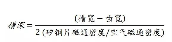
After deciding the slot opening size, the slot width is known, plus the width of the teeth and teeth of the silicon steel sheet flux density design value, can calculate the slot depth size. Commonly seen silicon steel sheet flux density design value of 1.6T (Tesla: represents the magnetic force flowing through the unit area), while the air flux density of 0.6T, which is 2.67 times worse; then the slot width minus the width of the teeth, and then divided by 2 to obtain the size of the unilateral, and then divided by the ratio of the air and the flux density of the silicon steel sheet of the difference between the proportion of 2.67, you can get assortment of the size of the depth of the groove, if in the boot part of the articulation with the teeth, and the teeth. If the design of guide angle or bevel is added to the interface between the boot and the tooth, the assorted slot depth size can be further shortened.
Tooth: Basically, we hope that the smaller the better, in exchange for more winding space, but mainly limited by the saturation flux density of the silicon steel sheet can accommodate the order, the common design flux density of 1.6 ~ 1.8 T, according to the specifications of the design of the motor flux size, calculate the width of the tooth. Once the width of the teeth is determined, the yoke and boot dimensions can be calculated according to the tooth size specifications and the above formula.
Conclusion
Silicon steel sheet in the motor is actually a magnetically conductive material application, so the main purpose is the magnetic conduction, therefore, in the design should be focused on the capacity of each part of the magnetic conduction is sufficient, to avoid a single part of the poor design of saturation, while the rest of the position is too much space to generate the situation, resulting in unnecessary waste. In actual motor design, it is necessary to consider other parameters, such as slot fill rate, magnetic strength and air gap size and other relationships.


