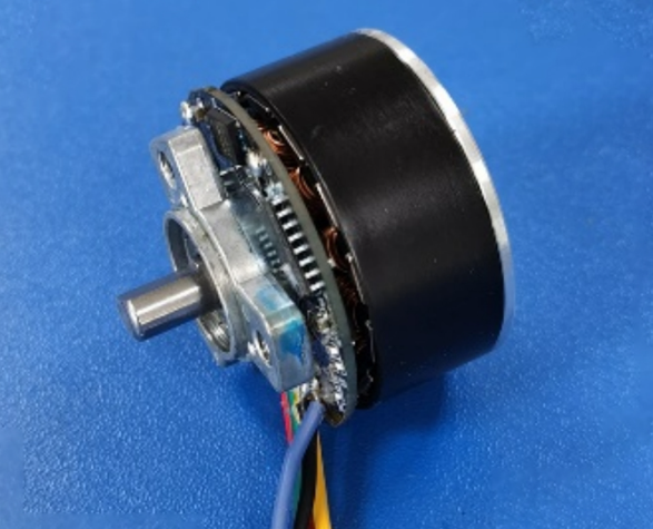
What are the common electrical faults and solutions for brushless motor motor automatic rotor skimmer?
Brushless motor motor automatic rotor skimmer common electrical faults and solutions are as follows:
1, power class failure
l Failure phenomenon: the equipment is completely unresponsive, the power indicator does not light.
l Failure causes
The external power supply is not connected or the voltage is too low or too high, and the fluctuation is beyond the permissible range of the equipment.
The internal power switch of the equipment is damaged and cannot conduct normally.
The power supply fuse is blown, and the circuit may be short-circuited or overloaded.
l Solution
Check whether the external power socket and power cord are well connected, use a voltmeter to measure the power supply voltage to ensure that the voltage is within the rated voltage range of the equipment.
Check the power switch and replace it if it is damaged.
Replace the fuse with the same specification, and at the same time, check whether there are any short-circuited or overloaded parts in the circuit, such as motors and drives.

2、Motor fault
l Failure phenomenon: the motor does not rotate or rotate abnormally, such as unstable speed, abnormal noise, serious heat, etc..
l Failure causes
Motor winding short-circuit, disconnection or ground fault, usually due to long-term use, insulation aging and other reasons.
Motor driver failure, such as driver internal components are damaged, parameter setting error, etc..
Excessive motor load, exceeding the rated load capacity of the motor, which may be caused by the jamming of the receiving mechanism or material blockage.
l Solution
Measure the resistance and insulation resistance of the motor winding using a multimeter or other tools to determine whether there is a short circuit, broken circuit or grounding fault, if there is a problem, the motor needs to be replaced.
Check the power supply of the driver, input and output signals, parameter settings, etc. If any components are damaged, professional personnel are required to carry out maintenance or directly replace the driver.
Check whether the receiving mechanism is jammed, foreign matter blockage, etc., clean up the material, adjust the receiving mechanism to ensure that the motor load in the normal range.
3、Sensor failure
l Failure phenomenon: inaccurate detection of the position of the material, resulting in abnormal charging action, such as charging untimely, wrong charging, etc..
l Failure causes
The sensor probe is covered by dust, oil and other pollutants, affecting the signal transmission and reception.
The sensor is damaged, such as internal circuit failure, component aging, etc.
The sensor installation position is offset, resulting in inaccurate detection position.
l Solution
Clean the sensor probe regularly to ensure that its surface is clean and free of impurities.
Use professional tools to inspect the sensor and replace it if it is damaged.
Re-adjust the installation position of the sensor, so that it is aligned with the correct detection position of the material, and calibration.
4, the control circuit class failure
l Failure phenomenon: the logic of the equipment running chaos, such as receiving the wrong order, action is not consistent.
l Failure causes
Relay, contactor and other control components are damaged, poor contact or adhesion.
The control line is aging and broken, resulting in signal transmission error or interruption.
PLC (Programmable Logic Controller) program error or failure.
l Solution
Check the contacts and coils of relays and contactors, and replace them promptly if they are damaged.
Check the control lines carefully, replace the aged and damaged lines, and make sure that the lines are firmly connected.
Check the PLC program to see if there are logic errors, improper parameter settings, etc. If necessary, modify and debug the program.
5、Communication faults
l Failure phenomenon: the receiver and the host computer or other equipment can not be normal communication between the data transmission interruption or error.
l Failure causes
The communication interface is loose, oxidized or damaged, affecting the signal transmission.
Communication line damage, such as cable breakage, short circuit, etc..
The communication protocol is set incorrectly, and the communication parameters of both sides do not match.
l Solution
Check the communication interface, clean up the oxidization on the surface of the interface, re-insert and remove the interface to ensure a good connection, and replace the interface if it is damaged.
Use a multimeter and other tools to detect the communication line, repair or replace the damaged cable.
Check the communication protocol settings to ensure that the communication parameters of the transceiver and other equipment, such as baud rate, data bits, stop bits and other settings are consistent.
※ If the above ways and means still can not solve the equipment failure, please contact the technical specialist of Xinhui Electromechanical Equipment Co.


