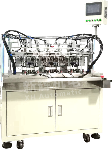
What are the common sensor failures and their solutions for brushless motor motor manual six-station external coil winder?
Brushless motor motor manual six-station external winding machine common sensor failure and its solution:
First, the position sensor failure
Fault phenomenon:
Inaccurate winding position: the winding machine is unable to accurately control the position of the winding during the winding process, resulting in untidy alignment of the turns, overlapping turns, uneven spacing or deviation from the intended position.
Failure of the automation function of the winding machine: For the winding machine with automatic positioning function, it may not be able to accurately move the winding head to the predetermined position according to the preset winding program, resulting in chaotic winding operation.
No signal output from the sensor: the winder may not be able to sense the winding position information at all, and the operation panel may display relevant error messages or alarm messages.
Cause analysis:
Sensor probe position offset: During the use of the equipment, due to vibration, collision or human misuse, may lead to changes in the position of the position sensor probe position, and the distance between the winding parts beyond the effective sensing range.
Sensor probe contamination: dust, oil and other pollutants in the working environment may adhere to the sensor probe surface, affecting its sensing sensitivity and accuracy.
Sensor component damage: the sensor's internal sensitive components (such as photoelectric sensors in the photodiode and light-emitting diodes, Hall sensors in the Hall components, etc.) may be damaged due to long-term use, over-voltage, over-current or aging.
Sensor line failure: the connection line between the sensor and the control circuit may be broken, short-circuited or poorly contacted, resulting in the signal not being transmitted properly.
Solution:
Adjust the sensor probe position: according to the operation manual of the equipment, use the appropriate tools to adjust the sensor probe position to the appropriate distance and angle to ensure that it can accurately sense the position information of the winding parts. Generally speaking, the distance between the photoelectric sensor probe and the sensing object needs to be precisely adjusted to a range of a few millimeters, while the Hall sensor should ensure that its relative position to the magnetic field source is correct.
Clean the sensor probe: Use a clean soft cloth, cotton swabs or special cleaning solvents to carefully clear off the contaminants on the surface of the sensor probe to ensure that the probe surface is clean and tidy, and to restore its normal sensing function.
Check and replace the sensor components: use a multimeter or oscilloscope and other tools to check whether the electrical parameters of the sensor components (such as resistance, voltage, output signal, etc.) is normal. If the component is found to be damaged, replace the sensor with the same model and carry out correct installation and debugging according to the equipment manual.
Check the sensor line: carefully check the sensor connection line, including plugs, sockets, wires and other parts, to find whether there is a broken circuit, short circuit or poor contact. For broken or short-circuited lines, to repair or replace; for poor contact, re-plugging or fastening the connection parts.
Second, the tension sensor failure
Fault phenomenon:
Unstable winding tension: In the winding process, the tension of the line is sometimes large and sometimes small, resulting in inconsistent winding tension, affecting the quality of winding, and may even be broken or slack line phenomenon.
Tension control failure: the winding machine can not be automatically adjusted according to the set tension value, or the tension adjustment range does not match the set value.
No signal output from the sensor: the winding machine is unable to obtain the tension signal, which may cause the winding operation to continue, but the winding tension is completely out of control.
Cause analysis:
Improper Sensor Installation: The tension sensor has been installed in an inaccurate position and may not be in close contact with the wire or winding components to accurately measure tension.
Sensor component damage: tension sensor in the strain gauge, pressure-sensitive components, etc. may be due to overload, fatigue, environmental factors or long-term use and performance degradation or damage.
Sensor line failure: The line connected to the tension sensor is broken, shorted or has poor contact, resulting in abnormal signal transmission.
Calibration problem: The initial calibration of the sensor is inaccurate, resulting in its output tension signal does not match the actual tension, affecting the tension control function.
Solution:
Reinstall and adjust the sensor: Check the installation position of the tension sensor to ensure that it fits snugly against the wire or winding component and can accurately measure tension. Depending on the requirements of the equipment, an adjustment device can be used to fine-tune the mounting position and angle of the sensor.
Checking and replacing the sensor element: Check the performance of the sensor by using a professional test instrument (e.g. strain gauge). If the strain gauge or pressure sensitive element is found to be damaged, replace the corresponding element or the whole sensor, and make sure that the replaced sensor has been calibrated correctly.
Check the sensor line: through visual inspection, multimeter measurements and other methods, to find out where the problem lies in the line. For line failure, repair or replace the damaged part in time to ensure that the signal transmission line is normal.
Recalibrate the sensor: the use of standard tension calibration equipment, in accordance with the calibration procedures of the equipment to recalibrate the tension sensor to ensure that its output tension signal accurately reflects the actual winding tension.
Third, the speed sensor failure
Failure phenomenon:
Inaccurate measurement of winding speed: the winding speed displayed by the winding machine has a large deviation from the actual winding speed, affecting the judgment and control of the winding efficiency.
Speed signal instability: the measured value of winding speed will fluctuate, resulting in the winding machine can not run stably, the winding process appears speed fast and slow.
No signal output from the sensor: the winding machine cannot obtain the winding speed signal, and the speed display on the operation panel may be zero or an error message may appear.
Cause analysis:
Problems with the sensor and rotating parts: There are problems with the installation between the speed sensor (e.g. encoder) and the rotating shaft or transmission parts of the winding machine, such as insecure installation, large concentricity deviation, etc., which affects the accuracy of signal acquisition.
Damaged sensor components: The code disk, photoelectric element or Hall element inside the speed sensor may be damaged, resulting in the inability to generate the speed signal normally.
Sensor line failure: the line connecting the speed sensor and the control circuit is broken, short-circuited or has poor contact, so that the signal cannot be transmitted.
External interference: surrounding electromagnetic interference may affect the transmission and processing of the speed sensor signal, resulting in unstable or incorrect signals.
Solution:
Adjust the fit between the sensor and the rotating parts: Check the installation of the speed sensor to ensure that it is firmly connected to the rotating parts and that its concentricity meets the requirements. This can be calibrated using a concentricity measurement tool to ensure accurate signal acquisition.
Check and replace the sensor components: Use multimeter, oscilloscope and other tools to check the components of the speed sensor, replace the damaged components, and pay attention to the installation direction and accuracy requirements of the components.
Check the sensor line: carefully check the connection line of the speed sensor, and exclude the situation of broken circuit, short circuit and poor contact. For lines susceptible to interference, shielded wires or additional anti-interference measures can be used.
Eliminate external interference: Check whether there are strong electromagnetic interference sources around the winding machine, such as large motors and frequency converters. Shielding, isolation or adjusting the layout of the equipment and other methods can be taken to reduce the impact of external interference on the speed sensor.
Fourth, counting sensor failure
Fault phenomenon:
Inaccurate counting of winding turns: the number of winding turns recorded by the winding machine does not match the actual number of turns, resulting in errors in the number of winding, affecting product quality.
Counting function failure: the winding machine can not count the number of winding turns, the counting display may always be zero or stop counting.
Unstable counting: The counting result of the number of winding turns will change randomly, which cannot accurately reflect the actual number of winding turns.
Cause Analysis:
Improper relative position of sensor to winding part: The sensing area of the counting sensor may not be properly aligned with the moving part of the winding part, resulting in loss of counting signal or false triggering.
Damaged sensor components: The photoelectric components, proximity switches, etc. in the counting sensor may have failed due to long-term use or physical damage.
Sensor wiring failure: Problems with the wiring connected to the counting sensor, such as breaks, shorts or poor contact, affect the transmission of the counting signal.
Software or Control Logic Problems: The signal processing software or control logic of the counting sensor may be faulty, resulting in an abnormal counting function.
Solution:
Adjust the sensor position: Adjust the position of the counting sensor to a suitable position to ensure that it can accurately sense the movement of the winding parts and generate counting signals. Adjust the sensing distance and angle according to different counting sensor types (e.g. photoelectric sensors, proximity switches, etc.).
Checking and replacing sensor components: Use multimeter, oscilloscope and other tools to check whether the components of the counting sensor are damaged, and replace the damaged components to ensure their normal operation.
Check the sensor line: look for broken, short-circuited or poorly contacted parts of the line and repair or replace them.
Check software and control logic: Check the control software or control unit of the winding machine to see if the program and logic related to the counting function are correct. If necessary, contact the equipment manufacturer or software developer for software update or repair.
※ If the above ways and means still can not solve the equipment failure, please contact Xinhui Electromechanical Equipment Co., Ltd. technical specialists through the page chat tool for help.


