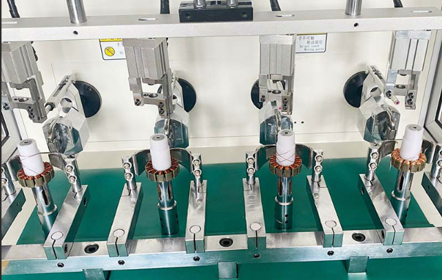
What are the common electrical faults and solutions for brushless motor motor manual four-station external winding machine?
Brushless motor motor manual four-station external winding machine common electrical faults and solutions:
First, the power supply related faults
1, the power can not be connected
Failure phenomenon: the machine does not respond at all, the power indicator does not light up, the operating panel does not show.
Cause analysis:
The plug is not plugged in or the socket is faulty, resulting in the equipment can not access the power supply.
The power cord is internally disconnected, probably due to long-term bending, wear and tear or external pulling.
The fuse inside the device is blown, this may be due to power surge, short circuit or overload.
The power switch is damaged and cannot close the circuit properly.
Solution:
First check that the plug is securely inserted into the outlet and try replacing the outlet to determine if the outlet is the problem.
Double-check the power cord for damage, and if it is damaged, replace it with a new one.
Locate the fuse box inside the unit and check to see if the fuse is blown. If blown, it will need to be replaced with a fuse of the same size, and check the circuit for short circuits or overloads.
Use a multimeter to detect the conductivity of the power switch, if the switch is damaged, it should be replaced in time.
2, power fluctuations or instability
Failure phenomenon: In the process of winding, the machine appears intermittent work, unstable winding speed or the operation panel display flashes abnormally.
Cause analysis:
External power supply grid instability, there may be too high, too low or frequent fluctuations in voltage.
The power module inside the equipment is faulty, such as rectifier, voltage regulator and other components are damaged, and the output voltage cannot be stabilized effectively.
Solution:
Install a voltage regulator or uninterruptible power supply (UPS) to stabilize the input voltage and ensure that the input voltage is within the range required by the equipment.
For internal power module failure, professional personnel are required to open the equipment shell and use a multimeter and other tools to check whether the output voltage of the rectifier, regulator and other components is normal. If the components are found to be damaged, they should be replaced according to the circuit diagram of the equipment and component specifications.
Second, the motor drive circuit failure
1, the motor can not start
Fault phenomenon: the motor of the winding machine does not show any signs of starting, even if the start button is pressed, the motor does not run.
Cause analysis:
The power transistor, field effect tube or integrated circuit chip in the motor drive circuit is damaged, and it cannot convert the control signal into enough drive current to start the motor.
The connecting wires between the drive circuit and the motor are broken, including the winding connecting wires, brush (if it is a brushed motor part) connecting wires and so on.
The control signal cannot be transmitted to the drive circuit normally, which may be due to the communication line failure between the controller and the drive circuit or the output signal failure of the controller itself.
Solution:
Use the diode test gear of the multimeter to check whether the power transistor, field effect tube and other components are normal, and for damaged components, replace them according to the model and specifications of the components. Check the power supply and input/output pin signals of the IC chip, if there is any problem, the chip may need to be replaced.
Check the connecting wires between the motor and the drive circuit, including checking whether the welding points are firm and whether the wires are broken. If there are any broken wires, re-solder or replace the connecting wires.
Check the communication lines between the controller and the drive circuit to make sure that the signal lines are connected correctly and that there are no shorts or breaks. Use an oscilloscope and other equipment to check whether the controller's output signal is normal, if the signal is abnormal, may need to repair or replace the controller.
2、Abnormal motor speed
Failure phenomenon: After the motor starts, the winding speed does not match the set value, either too fast or too slow, and can not be effectively adjusted through the operating panel.
Cause analysis:
Driving circuit in the speed components failure, such as speed potentiometer damage, PWM (Pulse Width Modulation) controller failure.
The magnetic field strength inside the motor changes, possibly due to demagnetization of the permanent magnets or damage to the magnetic field regulating element of the stator winding.
Changes in the motor load, such as jamming and increased friction in the mechanical transmission part of the winding machine, affecting the actual speed of the motor.
Solution:
Check whether the resistance value of the speed-regulating potentiometer can be adjusted normally, and replace the potentiometer with the same specification if it is damaged. For the PWM controller, check its input and output signals, use an oscilloscope to observe whether the frequency and duty cycle of the PWM signal meet the requirements, if there is any problem, it may need to be reprogrammed or replaced.
Use a gaussmeter to measure the magnetic field strength inside the motor. If the permanent magnet is demagnetized, it may be necessary to replace the permanent magnet part of the motor. Check the magnetic field regulating components of the stator winding, such as whether the connection of the magnetic field winding is normal or not, and whether the current regulating components are damaged or not.
Check the mechanical transmission part of the winding machine, including the tension of the belt, the meshing of the gears, and the lubrication of the bearings. Clean up, lubricate or replace the corresponding parts of the parts that appear to be stuck or have increased friction in order to reduce the motor load.
Third, sensor failure
1、Position sensor failure
Failure phenomenon: during the winding process, the positioning of the thread is inaccurate, the spacing between the turns of the thread is not uniform, or the position of the winding deviation.
Cause analysis:
The distance between the probe of the position sensor and the winding components is not appropriate, may be too close to cause collision damage, or too far away to accurately sense.
The sensor itself is damaged, the internal sensing element, circuit components failures, such as Hall component damage, coil breakage.
Problems with the connecting wires between the sensor and the control circuit of the winding machine, such as loose, short or broken.
Solution:
Adjust the distance between the position sensor probe and the winding components, usually according to the installation instructions of the sensor, the distance will be adjusted to the appropriate range, usually in a few millimeters.
Use a multimeter to check the resistance, voltage and other parameters of the sensor to determine whether the internal components of the sensor are damaged. For damaged sensors, replace the sensor with the same model according to the equipment requirements.
Check the connecting wires between the sensor and the control circuit to make sure that they are firmly connected and that there are no loose, short-circuited or broken wires. If there is a problem, reconnect or replace the connection line.
2, tension sensor failure
Failure phenomenon: unstable winding tension, the line may be too loose or too tight, resulting in a decline in the quality of winding, and may even be broken.
Cause analysis:
The probe of the tension sensor is not in good contact with the line, or installed in the wrong position, can not accurately perceive the tension of the line.
The sensor itself is damaged, and the characteristics of its sensitive components such as strain gauges change, or the signal processing circuit is faulty.
The connecting wire between the sensor and the control circuit is loose, short-circuited or broken, resulting in the signal not being transmitted properly.
Solution:
Check the installation position of the tension sensor probe to ensure that it is in close contact with the wire and can sense the tension correctly. The position and angle of the probe can be adjusted appropriately.
Use standard tension test equipment to measure the tension of the wire at the same time as the tension sensor and compare the results. If the deviation is large, use a multimeter to check the resistance value of the sensor and other parameters to determine whether it is damaged. For damaged sensors, replace the sensor with one of the same type.
Check the connecting wires between the sensor and the control circuit to ensure smooth signal transmission. If there is a problem, reconnect or replace the connection line.
Fourth, the control circuit failure
1, control chip failure
Failure phenomenon: the winding machine can not be in accordance with the preset program for winding operations, such as winding mode confusion, can not automatically switch station, etc., and the operating panel may display an error code or no response.
Cause analysis:
The control chip may be damaged in the internal circuit due to abnormal power supply, static electricity, overheating and other reasons.
The pins of the chip may have false welding, short circuit, etc., affecting the normal input and output of the signal.
Solution:
First check whether the power supply of the control chip is normal, make sure the voltage is stable within the range required by the chip. If the power supply is normal, use professional electronic testing equipment, such as logic analyzers, etc., to check whether the input and output signals of the chip are normal.
For the case of false welding of pins, it is necessary for professionals to use welding tools to re-weld the pins. If the chip is found to be internally damaged, according to the chip model and equipment requirements, replace the same control chip, and re-burn the program and parameter settings.
2、Control panel failure
Failure phenomenon: the keys on the operating panel are out of order, the display appears garbled, black screen or can not normally display the winding parameters and so on.
Cause analysis:
Control panel keys may be due to long-term use leading to poor contact, wear and tear of the internal conductive rubber or key under the microswitch damage.
The display may not be able to display properly due to loose or damaged wires or faulty display driver circuit.
Problems in the communication line between the control panel and the control circuit, such as broken connecting wires or electromagnetic interference.
Solution:
For key failure, open the control panel (if the user is allowed to disassemble it) and check the microswitches and conductive rubber under the keys. If the conductive rubber is worn, you can replace it with a new one; if the microswitch is damaged, replace it with a microswitch of the same specification.
Check whether the wires of the display are firm; if they are loose, re-insert and plug the wires. If the wires are damaged, replace them with new ones. Use a multimeter to check whether the components of the display driver circuit are normal, if damaged, replace them according to the component specifications.
Check the communication lines between the control panel and the control circuits to make sure that they are firmly connected and not subject to electromagnetic interference. Shielded wires can be used to minimize electromagnetic interference, or filtering circuits can be added to improve signal quality.
※ If you still can't solve the problem by the above ways and means, please contact the technical specialist of Xinhui Electromechanical Equipment Co., Ltd. through the page chat tool to seek help.


